| Index | wersja polska
|
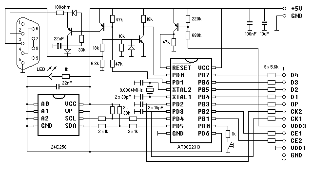
This device attempts to emulate the original FA-3 cassette interface and the FP-12S thermal printer. Files are stored in an onboard EEPROM or transferred through the serial port, depending on the software version. Data directed to the printer are transmitted through the serial port or an optional parallel port, again depending on the software version.
The project uses an AVR RISC microcontroller, because not any
standard CISC chip could handle the traffic on the bus.
Powering the EEPROM from the port pin may look unusual, but this
reduces power consumption, and allows EEPROM "hot swapping"
like a tape cassette.
The series resistors on the bus protect both the calculator and the
microcontroller in case of bus conflicts (when something goes wrong),
or when the device is not powered.
The resistors on pins PD2 and PD3 pin along with the 15pF capacitors
also work as low pass filters eliminating noise.
Without them the circuit doesn't work reliable.
Any general purpose small signal diodes and transistors can be used,
for example:
diodes - 1N4148
transistors pnp - 2N3906, BC557
transistor npn - 2N3904, BC547
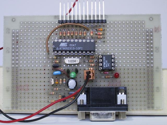
Due to its simplicity, the device was built on a piece of prototype
board.
It needs a separate power supply of ca. 5V, because it draws too much
current to be powered from the calculator.


This software version uses a serial EEPROM chip as storage medium.
Incoming data aren't processed in any way, they are stored in the
EEPROM sequentially as they are received.
Idle strings and start/stop/parity bits aren't recorded.
An attempt to LOAD from an EEPROM containing bogus data will
not be prevented, but will give unpredictable results.
Most likely they will be ignored, because the calculator expects some
specific data format, and performs some basic checks.
Every LOAD, SAVE, or VER operation advances the
file pointer, so it needs to be "rewound" before the stored
file can be LOADed or VERified (just like a tape).
To "rewind" the file pointer back to beginning press the key
on the PB0 pin, or switch the calculator off and on.
LED indicates memory access, memory overflow (equivalent to tape end)
causes ERR9.
Printed data are converted to ASCII, and sent through the serial port. The output can be fed to a PC running a terminal program, or directly to a printer featuring serial input (tested with a Brother M-1109).
The program was tested with the FX-700P and the FX-730P models.
![]() tape25d.zip - AVR source code
tape25d.zip - AVR source code
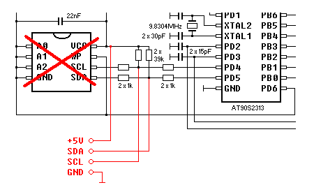
This software version can transfer files through the serial port between the calculator and a PC. It also supports a standard parallel printer connected to an optional parallel port controlled through the I2C bus. The EEPROM isn't supported any more and has to be removed. Required circuit modifications are marked red on the image below.

The interface transfers unprocessed 12-bit data, along with the
start, parity and stop bits.
A 12-bit data word has to be split up in two 6-bit chunks to be able to
pass an 8-bit transmission channel.
Then a fixed value of 0x30 is added to each to make them printable
characters.
The least significant character is transferred first.
Characters outside the 0x30-0x6F range are allowed between a pair of
valid characters.
They can be used to synchronise the data stream (to mark the least
significant character of the pair).
The program was tested with the FX-700P and FX-730P calculators.
![]() tape27h.zip - AVR source code
tape27h.zip - AVR source code